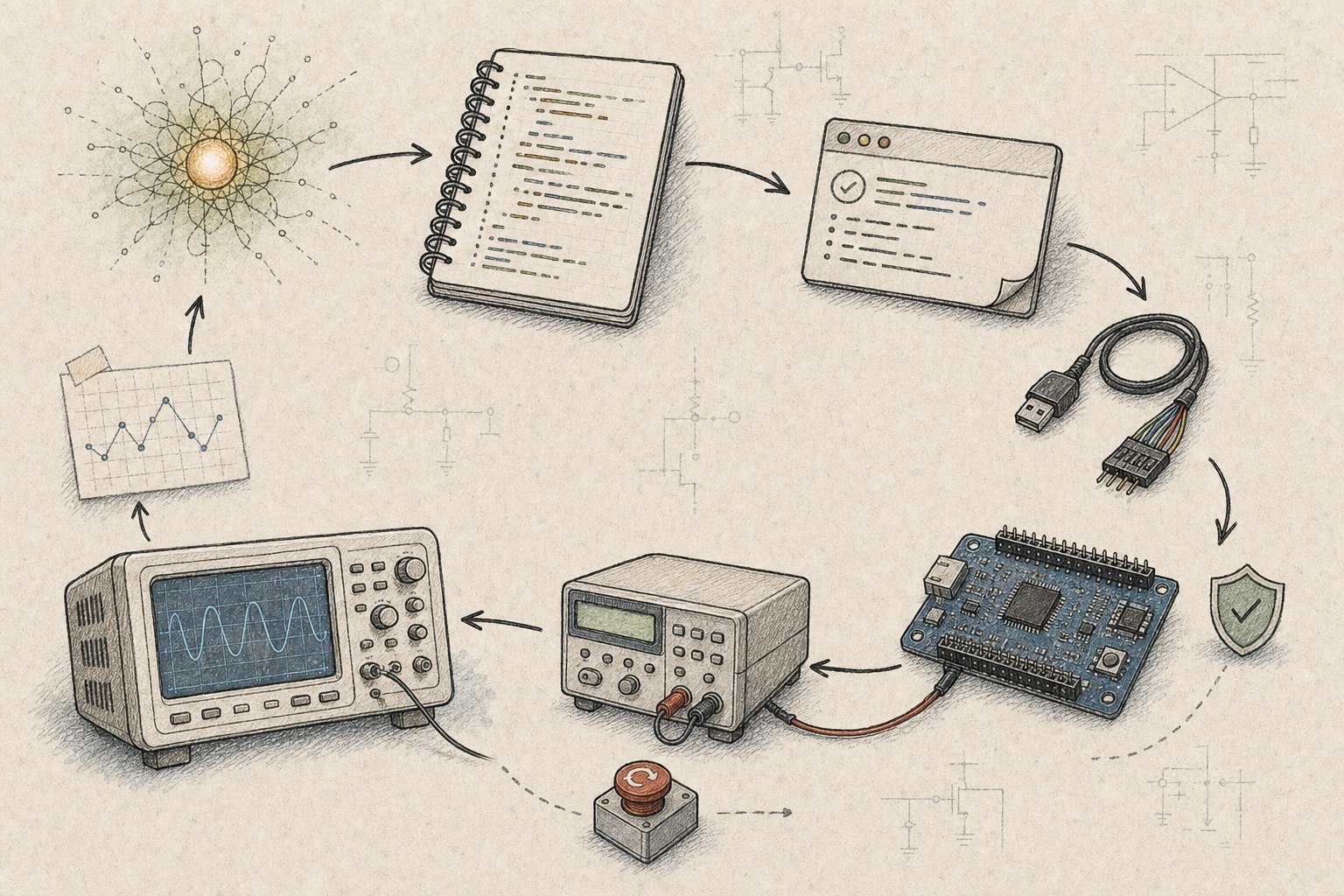
“Use AI to test the board” sounds simple until the board is on the bench.
The model can propose a code change, but it cannot see the UART cable. It does not know which serial port belongs to the current fixture, whether the electronic load is already active, whether the programmer flashed the intended image, or whether a measured voltage is safe for this revision.
The hard part is not connecting a chat box to an oscilloscope.
The hard part is building a controlled path from intent to physical evidence.
The First Version Was Remote Button Clicking
My early automation wrapped individual tools:
- run the compiler;
- flash a board;
- open a serial port;
- send a command to a protocol instrument;
- save a logic capture;
- take a screenshot.
That was useful, but it was still a collection of remote buttons. The output of one tool was not a reliable input to the next. A successful process exit did not prove that the correct target had been flashed. A screenshot was visible to a person but difficult for an agent to evaluate.
The system became more useful when every action began returning evidence with identity and context:
target: fixture-02
device_id: expected-device
firmware_sha256: ...
flash_result: PASS
uart_start: 2026-07-26T09:31:04+08:00
stimulus: request 9 V / 2 A
measured_vbus: 8.97 V
protocol_result: ACCEPT
abort_triggered: false
Now the agent was not merely operating tools. It could compare an observation with an acceptance contract.
A Closed Loop Has Six Layers
My current mental model has six layers.
1. Intent
The engineer defines the goal, boundaries, and what counts as success.
For example:
Correct the state transition so the device accepts a valid power request, without exposing the next operating state before authentication completes.
This is deliberately more precise than “fix charging.”
2. Project knowledge
The repository explains:
- system topology;
- state ownership;
- protocol terminology;
- safety limits;
- build variants;
- source anchors;
- known hardware differences;
- required evidence.
Without this layer, a stronger model simply makes a more confident guess.
3. Software tools
Build, static analysis, host tests, ELF inspection, and packaging must be callable and return meaningful results. An agent needs the failed target and first useful diagnostic, not five megabytes of terminal noise.
4. Target control
The Harness must identify, flash, reset, and recover the DUT. Image hashes and target identity matter because “flash succeeded” is worthless if the wrong binary reached the wrong board.
5. Stimulus and measurement
For USB-PD work, I use different tools for different roles:
- an actively controlled instrument can enter protocol modes and request fixed or programmable power profiles;
- a protocol analyzer can capture and decode traffic;
- a power supply or load establishes electrical conditions;
- UART exposes internal state;
- a scope or logic analyzer captures timing and waveforms.
One instrument does not automatically replace another. Capture is not control, and a negotiated current is not the same as an electronic load.
6. Evidence and decision
The Harness compares the observed sequence with explicit assertions and preserves the artifacts needed for review.
and acceptance"] A["AI agent"] R["Repository contract"] B["Build and host tests"] F["Flash and reset"] S["Protocol and electrical stimulus"] M["UART, analyzer, scope"] E{"Evidence passes?"} X["Revise or diagnose"] P["Prepare review"] G --> A A --> R R --> B B --> F F --> S S --> M M --> E E -- no --> X X --> A E -- yes --> P
Capture Is Not Control
This distinction caused more confusion than I expected.
A USB-PD analyzer may read HID reports, parse protocol messages, and display beautiful packet traces. That proves an acquisition and decoding path. It does not prove that a PC API can transmit a request, change roles, trigger PPS, or advertise Source capabilities.
Meanwhile, another bench tool may expose serial commands for:
- reset;
- entering PD mode;
- requesting a fixed PDO;
- requesting PPS voltage and current;
- exercising UFCS or legacy charging protocols.
That is active stimulation, but it still may not provide precise electrical loading or independent capture.
My practical architecture is complementary:
use the active tool to stimulate the DUT, the analyzer to observe the exchange, and dedicated instruments to measure the electrical result.
The Harness records which instrument supplied each piece of evidence.
Define the Experiment Before Running It
An agent should not improvise indefinitely on powered hardware. I describe each hardware task as a bounded experiment:
goal: verify authenticated transition to the requested power state
preconditions:
  - fixture identity matches
  - DUT input is off
  - electronic load is disabled
limits:
  max_vbus_v: 12.0
  max_current_a: 2.2
  max_temperature_c: 70
  max_attempts: 3
stimulus:
  - power_on
  - wait_for_boot
  - request_profile
evidence:
  - UART state sequence
  - protocol accept message
  - measured VBUS range
abort:
  - overcurrent
  - overtemperature
  - unexpected source role
cleanup:
  - disable_load
  - power_off
The exact format is unimportant. The important point is that limits, pass conditions, and cleanup exist before the first relay clicks.
One Practical Debugging Loop
A useful session can look like this:
- read the project contract and locate the owning state machine;
- build a clean baseline;
- reproduce the failure with a named stimulus;
- capture UART state, protocol traffic, and voltage behavior;
- add temporary instrumentation around the ambiguous transition;
- rebuild and flash a hash-identified image;
- repeat the same stimulus;
- change the smallest responsible behavior;
- run host tests and rebuild all affected configurations;
- repeat the hardware experiment;
- remove temporary logs;
- preserve the final evidence and residual risk.
This loop is already recognizable to a firmware engineer. The AI contribution is speed across the interfaces: reading the code, proposing where to instrument, operating repeatable tools, comparing logs, and keeping the evidence attached to the exact revision.
What the Agent Still Cannot Claim
A clean build proves buildability for that configuration.
A host test proves logic under the assumptions of the host model.
A UART trace proves that particular firmware reported a sequence.
A protocol capture proves what appeared on the bus during that run.
A waveform proves an electrical behavior under the recorded setup.
None of these proves everything.
In one recent repair, source review and targeted builds supported the state-machine correction, but production hardware confirmation remained outstanding. The correct report was not “fixed.” It was:
source validation passed; verify the production authentication exchange and state ordering on hardware.
That sentence is less satisfying than a green check mark. It is also honest engineering.
Make Failure Safe and Informative
Physical automation needs stricter failure behavior than ordinary scripts.
Every actuator should have:
- an allowed range;
- a timeout;
- a known safe state;
- a cleanup action;
- a way to verify that cleanup occurred.
Every observation should include:
- timestamp;
- tool configuration;
- target identity;
- firmware identity;
- units;
- raw artifact location;
- parsing or threshold rules.
If a tool returns only failed, the agent cannot reason about the next step. If it returns the failing stage, target, command, captured log, and cleanup status, the failure becomes useful evidence.
Start with One Observation
An autonomous lab is not the starting point.
The highest-leverage first step is often UART:
- make build output reproducible;
- make flashing identify the image and target;
- capture UART with timestamps;
- define one repeatable stimulus;
- assert one meaningful state transition.
Then add controlled power, protocol instruments, relays, loads, and scopes only when the task needs them.
The goal is not to let the AI touch every instrument.
The goal is to let it complete one meaningful engineering loop and show exactly why the result should be trusted.
That is the path from prompt to oscilloscope.